Auto Sequence, Sources, and Fields
Learn how to create an auto-sequence ray path and define source/field properties.
Transcription:
In this video, I would like to show you how we trace here these rays through our system.
The system I’ve opened is here, the zoom lens system, and you can find it here under the example folder.
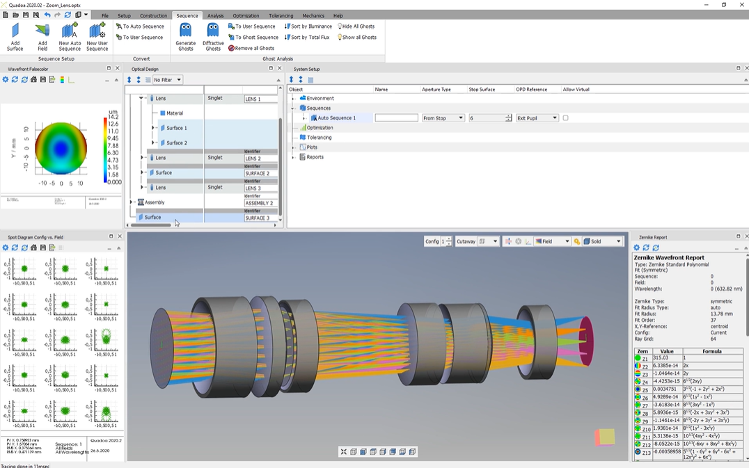
To trace here these rays, we have to open here the system setup.
You can open the system setup here under the Windows icon. Just click here in system setup.
If we take a look at the system setup, we see here this title sequences.
And if we open the sequences, we see that here’s an auto sequence inserted.
So the default setting is always set to auto sequence, And an auto sequence means that our our rays will start at the first surface of our of our system and they’ll end at the last surface of our system.
So the rays pass from the top through the bottom every surface. So starting at the first surface, then pass through the second surface, which is the surface here highlighted in red of our first lens, then pass through the second surface of our first lens, and so on until the rays reach the last surface, which is c highlighted in red.
So this is always the default setting, which means the rays start at the first surface, go through the system through every surface, and are ending at the last surface.
If we take a look at the auto sequence here in the system setup, we can open the auto sequence, and here we can define the source.
So we can define the source type, whether it should be, for example, a plane wavefront where the the rays are coming from the infinite, or, for example, a point source. So we have, only a point as a source, or we for example, we can download also a ray file and insert a ray file, as our source type.
Here we can define the wavelength, for example, two wavelengths.
If we open here the source, we can here specify our distribution of our rays. So in this example, we have a rect grid, but you can change it also to a ring distribution or to a single ray distribution.
Here, we can select how many rays there should be traced. So in this case, ten rays for each field.
And here we see we have five fields. You see them also here, the five different fields.
And here we can define the tilt of the field, for example, two point five degrees tilt in the y direction.
So we can change the tilt to ten degrees, and we see that here the tilt has been increased.
If you would like to add more fields, you can just click here with the right mouse button and select, add field or you go here to the sequence menu and just click here on the add field icon.
Thank you for watching.