Automotive Heads-Up Display (HUD)
Learn how to design an automotive HUD including CAD import of a windshield, defining the driver’s eye box and virtual image, optimizing a freeform surface, and analyzing image quality and sunlight impacts.
Transcription:
Hello, and welcome everybody to another tutorial.
Today, we are going to design a head up display as it is used in the automotive industry. We will start our design by setting up the windshield. For this, we will use the singlet element. We will assign the material as well as the thickness to it. And then we specify the aperture, which is a rectangular aperture in this case. We enter the size of the aperture, and we duplicate it so we can assign it to the second surface as well. Now since the windshield is tilted, we will rotate it around the x axis.
And in the next step, we now can import the real shape of the windshield.
For this, we will import it from a, point cloud, which I have primary, to this video exported from the mechanical cut software.
For this, we go to the surface, right click on it, add form, import point cloud. Here, we select the, point cloud file.
We click on okay. Now we need to assign the polynomial that we want to use for the, polynomial fit.
We specify the polynomial order, set all the coefficients to variables, and convert the point cloud. And as we can see, we have basically a zero fit error here, and we will do the same thing for the second surface as well. So, again, add form, import point cloud.
And now we have our windshield with the imported, shape from the mechanical cat. After setting up the windshield, we will, set the identifier just for convenience to windshield, and we will add two additional surfaces, one for the air box and a second one for the virtual image.
And we placed the virtual image here in front of the windshield, and we want all of them to be in absolute coordinate space. So we change this here to absolute. Now we specify the position of the virtual image. So this one should be two and a half meters away from the windshield, and we want it to be a bit down towards the street by three hundred fifty millimeters and also a bit rotated towards the street.
The driver’s head is positioned to the left away from the windshield.
And, also, we want, since the driver is not sitting at the center of the windshield but to the side, we add the displacement of the windshield, and, also, we move it a bit downwards.
We now, set the aperture of the eye box, which is a rectangular aperture of one hundred and twenty by sixty millimeters in our case.
And now we can set up our first sequence. We will use a user defined sequence, and the light will start at the virtual image. And then it will go to the I box, And the iBox will be used as the, stop surface.
And here, we can also see that the iBox is selected as stop surface, and we will use a, rectangular grid for the rays.
And to rasterize the virtual image, we will add additional fields at all the corners and some, to the side of the image. For this, we will just add some fields or by pressing, the insert button.
And here we can, enter the, the centering of the, field points.
As well one on top and one on the bottom.
And as you can see now, we have, like, all these, field points, and they’re all traced to the aperture of the I blocks.
Now since everything here is off axis and also the rays get reflected at an angle from this, freeform windshield, We will add a dummy surface down here, and we will align the surface to the chief ray. And this will be our reference ray for the, positioning of all the head up display optics.
So we add another surface here.
We also want to position it in absolute coordinate space, and we move it downwards.
And, also, we already rotate it for the course alignment.
And now the other rotation and fine adjustment will be done, using, the optimization.
So first, we, make our sequence to trace the race to this dummy surface. Therefore, we add another surface.
First, we need to reflect at the windshield and then another surface, which is our dummy. And here, since we want to reflect, we need to select reflection.
And as you can see here now, the rays already get traced down towards the dummy surface. However, it’s not aligned yet. Now to align the surface with our chief ray, we will, set up a merit function.
Here we first add a ray trace.
And in the ray trace, we specify the, position of our chief ray to be at the center of the surface.
For this, we add this chief ray position goal.
We select the dummy surface as where we want to position it, and the y coordinate should be zero.
Then the same thing for the x coordinate.
Further, we want the, g Fray incident angle on the surface to be, zero as well.
So we add a goal for this.
And since we also want to align the rotation of the surface, we will select the chief ray of this outer sequence here. For this, we add an other chief ray position goal, And now we select the outer field, which is, the yellow one here.
And we want this one also to align at the x zero coordinates in the, at the dummy surface. Now we go to the dummy surface, and here we set all the variables. So the z position is a variable, the x position is a variable, as well. All the rotations are variable.
Now in the optimization tab, we go to the local optimizer, and we run it.
And as we can see, now the surface is perfectly aligned with our g frame also in rotation, but also in the x y position.
Now we’re done with the setup of all the, elements like the windshield, the eyeballs, and the virtual image, as well as our reference surface.
And from this point, we now can start with the actual design of the head up display.
One of the challenges for head up display design is that typically the, building area where the optics need to fit into is constrained by the design of the dashboard and the building area that is available there.
And to take this into account, we will start by importing the bounding box of the building area that we’ve prior to this video exported from the mechanical software.
For this, we go to the, mechanics tab here.
We add a file, and I have already placed it in the, model folder. We can just select this here, and now this will be the building area that we want to fit the head up is display into.
The design for the head up display itself will be, one freeform surface as well as one fold mirror and finally the display. And for this, we will add three additional surfaces.
And we’ll name them, like, free form mirror, fold, and display.
Now we need to position these three, surfaces in the building area. And prior to this video, I have already found some parameters that position them nicely inside here, and I will just enter these parameters. You know?
And as we can see now, we have arranged the coordinate spaces for the surfaces. And in the next step, we now can adjust our sequence to trace over these surfaces.
Now in the sequence, we add three additional surfaces, and we want the light to first be reflected at the freeform surface, then at the fault mirror, and finally, the display is our image surface. And, of course, the action here should be reflection in both cases.
Now we can see the light is already traced up to the, display surface.
For the description of the freeform surface, we will add a polynomial, form here, and we will set the order of the polynomial up to the fourth order. Now for the optimization of the freeform surface, we will add an additional merit function.
And what we want to optimize here is just the spot radius.
Now in the optical design editor, we switch the merit function so we can assign the variables to the second merit function.
For the polynomial form, we want to set all the, coefficients as variable. However, we want to exclude the piston term as well as the tilt terms since the tilt will and the piston will be rotated about the, by the position and the, rotation of the surface itself. Now that we are done with the setup of the merit function, we can open a, spot diagram plot so we can see what is happening.
And then we just run the optimization, and we already have our optimized freeform surface.
Now we can optimize the design a bit further. As we can see here, the, area is a bit close to this, wall here.
For this, we will rotate the, mirror up by a bit.
And now we just run the optimization again.
And, also, we want the display surface to be centered on the central chief ray. So we add this, operand to the merit function. Again, we add this, chief ray goal on our display surface in y direction, and we set this as a variable here.
Now if we look further at the design, we can see that the angle of incidence of the chief ray here on the display surface is a bit steep.
We do not want to beat this autogonally because then the sunlight that is coming through the windshield might reflect from the display into the eye of the driver, but we just wanted to have a bit smaller angle. And therefore, we just apply some additional rotation to it and to some reasonable value, and we run the optimization again.
And so we’re done with the basic optimization.
Now we will add some approaches to all these elements. For this, we will hide the mechanics so we get a better view on the, optics.
And here we add rectangular approaches.
And we repeat this for the other surfaces as well.
And we can now also hide this dummy surface because we do not need it here anymore.
Now that we are done with the optimization, we want to analyze our image quality. And at the moment, we are just using the sequence from the virtual image down to the display for the optimization. But, of course, in the, real system, the light comes from the display, and then it’s just seen at the virtual image. So it goes the other way around.
Also, one difference is that the aperture here is not the whole eye box for the rear system, but it’s the pupil of the eye of the driver.
And for this, we will add a second sequence.
To add the second sequence, we will not set up a whole new sequence, but we will duplicate the, existing sequence.
And then we will revert the sequence direction.
Now we will hide the original sequence so we can better see what we’re doing. And what we need to do here now is to adjust the fields because the fields of the real sequence just are the size of the, display surface.
So let’s adjust the fields here.
And now we have this sequence that is starting here and going in this direction and finally to the, virtual image.
For the aperture of the driver’s eye, I will add another surface directly after the eye box.
We’ll set it to relative, and the surface will be the eye.
And it has an aperture of three millimeters.
And now for the sequence, we will change the surface that is the stop surface from the eye box to the eye.
Now at the moment, as you can see here, the rays are drawn as virtual, which you can see from the dashed lines. And this is because the z coordinate of the last surface is showing in this direction, and the race will always start, like, in positive z direction.
To change this, we can simply go to the last surface and rotate it by one hundred and eighty degrees around the x or y axis. Now we have, like, this drawing style that we see here are the real rays.
Then they go to the the, eye and the aperture. And then here, we see the virtual rays going to the virtual image.
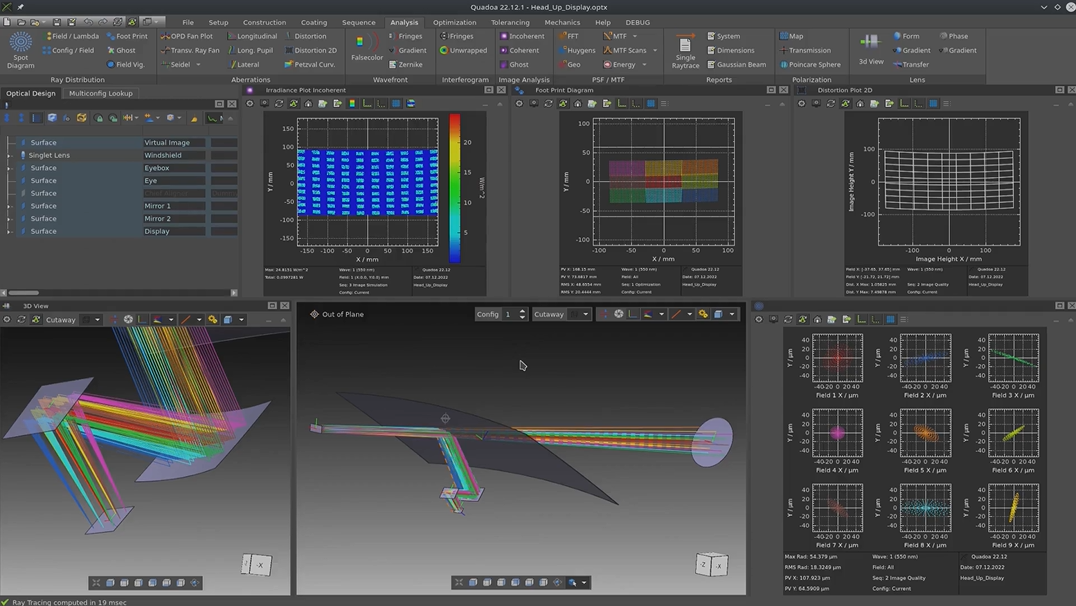
Now to see the spots of the, second sequence that shows the, real light path from the display over the human eye to the virtual image, we just select the second sequence.
Now here, we can see the spots for the virtual image.
And we can also analyze further things. For example, we can look at the footprint diagram, which is the distribution of the rays on the freeform surface, or we can also look at the distortion of the image.
And, of course, any other of the available analysis property.
Now one last thing I want to do is to check if there could be any light that is coming from the sun through the windshield then reflecting at the mirrors reflecting at the display and going back over the mirrors into the eye box so the driver could be blinded.
For this, I will add an additional user defined sequence.
The sequence will start at the eye box.
So we’re tracing the race backwards.
Then we go to the windshield.
We will trace a plane wave front.
The I box will be the stop surface, and the rays will taken from the stop surface with equal grid.
Now we need to adjust, the field.
And here from the surface, we want to reflect the light down over these two mirrors to the display.
So we just add the surfaces. We can skip the dummy because nothing is happening there.
And we need to set them all to reflection.
Now from down here from the display, we go back up and try to get out of the windshield towards the sun, which is just the backwards path the light would normally go.
So, again, we add some surfaces, and the windshield.
And as we can see now, the light here is just reflected there, and it doesn’t get any further.
However, if the display wouldn’t have been tilted in the design at the beginning, then we could see that if we just rotate it back, we could get these rays going through up to the windshield, and this would allow a path where the sunlight can get from the sun over here over the mirror to the driver’s eyes. However, as we can see in our design, this is not possible because the reflection will just go here and will be dumped into the housing.
So I’m already at the end of this tutorial.
I hope you learned something new, and see you next time.