Pivot Points
Learn how to define offset pivot points for an optical component.
Transcription:
In this video, I will show you how to set up pivot points for single lenses or for whole assemblies.
With the high level element structure of Quadrua, it is is possible to set up mechanical dependencies of the elements and assemblies in the model in perfect analogy to the real world.
And by setting up those pivot points for single elements and whole assemblies, it is possible to model and simulate the mechanical dependencies for the tolerance analysis in a very intuitive way, and it takes just few minutes and saves for that a lot of time.
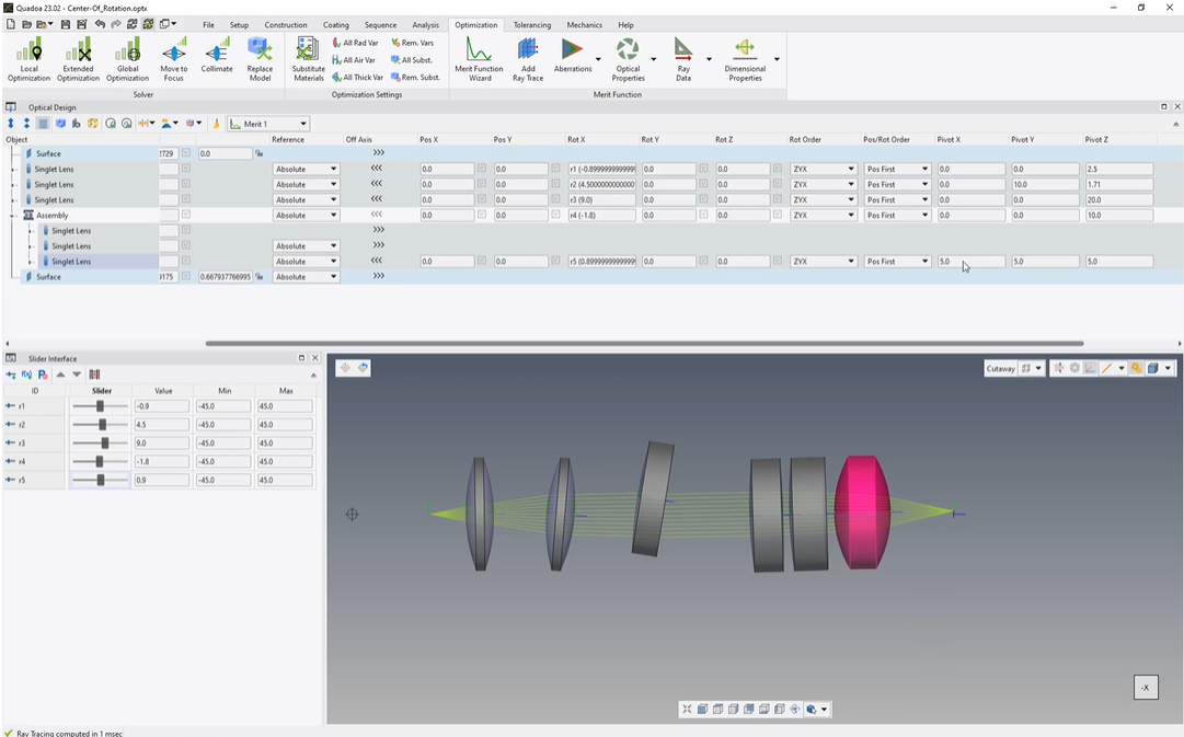
So in this model, I set up, five different pivot points, one pivot point for each of these three lenses, then one pivot point for this assembly, and one pivot point for this lens inside the assembly.
So I’m assuming here that these three lenses are mounted together, and for that, I’ve assigned them to a common assembly.
To set up pivot points, we go here to the optical design editor, and then we click on the element for which we would like to define the pivot point. Then we click here on this off axis arrow, and then we scroll to the right. And here we can see these options for the pivot point.
And there we can insert the coordinates of the pivot points. So in my case, it’s the coordinate x zero, y zero, and c two point five. I’ve entered a parameter here for the rotation around the x axis, and I’ve inserted here the slider with this parameter.
And for that when I’m sliding here, I will see that here this lens is rotating around the pivot point.
So the pivot point here of this first lens is set up that it will rotate around its own center.
The second pivot point is here at these coordinates, x zero, y ten, and c one point seven.
And when I am sliding here with the slider, I will see that the lens will rotate around the upper right corner of the lens.
Here the third, lens will rotate around the center of curvature of the first lens.
And here when I’m sliding here with this fourth slider, I will see that here this whole assembly is rotating around its own center assuming that, for example, these lenses here are mounted together in one assembly.
And of course, it’s possible to set up, a single pivot point for a single lens inside an assembly.
So you can see here this lens has this pivot point here, five, five, five coordinate.
And when rotating here with this sliding here, you can see that it will rotate around this pivot point.
So this means that with these pivot point options, it is possible to design and tolerance the optical system as it will be in the real world and setting up different mounting options for each single element to take in account the mechanical dependencies of elements and assemblies.
Thanks for watching.