Freeform optics are a category of optical components whose unique shapes provide utility in a wide range of applications. They first began to be used in illumination applications in the 1990s and later in imaging applications in the late 2000s. They offer benefits such as improved optical performance and reduced size. Often a single freeform component can replace multiple traditional optical components. They have enabled and revolutionized products such as short throw digital projectors, automotive heads up and near eye displays. They are challenging from both design and manufacturing perspectives. These challenges are what prevented freeform optics from being more widely used earlier. In this article we’ll discuss capabilities in Quadoa Optical CAD that enable faster design and more efficient simulation of freeform optics.
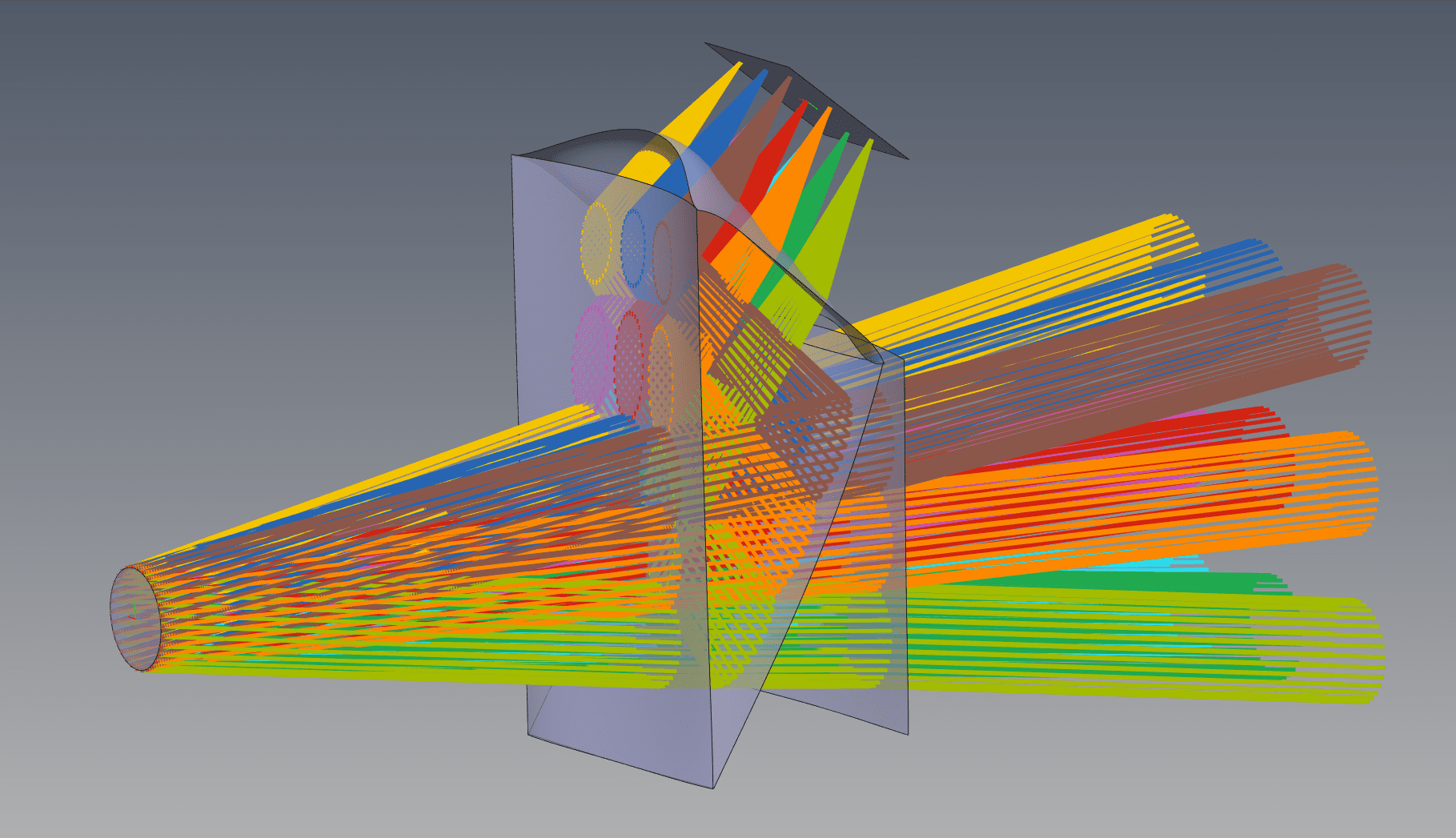
From a modeling perspective, freeform optics complicate the traditional way of modeling optical systems, which uses a sequential list of surfaces each positioned relative to the prior surface. Freeform optics can have radically different shapes and numbers of surfaces. It is critical that they be defined with an object-based optical model, such as that used in Quadoa. When freeform surfaces are optimized, it is important they be independently positioned to allow the optimization routine isolated control of each surface. This requires complex coordinate shifts and solves in traditional optical design programs, but it is the native paradigm in Quadoa. Similar to mechanical CAD programs, Quadoa’s paradigm has surfaces positioned in relative or absolute coordinates, and hierarchically grouped into components and assemblies. The image below illustrates how a 4-surface freeform prism is modeled with surfaces positioned in absolute coordinates, but referenced to a parent object that can also move as a single entity.

Another complication when modeling freeform optics is the violation of paraxial assumptions that makes tracing rays and calculating optical properties difficult. Choosing the right rays to aim at the pupil of the optical system and calculations such as focal length can be problematic when using paraxial assumptions. An efficient way to speed up raytracing is to model systems backwards such that the pupil is close to the front of the optical system. Quadoa goes further with a raytrace engine written without any paraxial assumptions, so it doesn’t aim rays at a paraxial entrance pupil by default. During freeform optimization, the ability to quickly trace rays without paraxial assumptions is beneficial. In addition, defaulting to work with real (rather than paraxial) optical properties is also more meaningful for these types of systems.
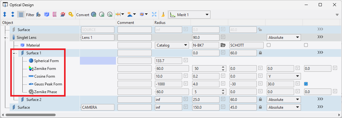
There are various methods employed to define freeform optical surfaces. By definition they are comprised of asymmetric surfaces implemented in various ways: high-order aspheric XY polynomials, combinations of multiple form profiles, or point clouds. Quadoa provides the capability to define freeform surfaces in all these ways. The XY polynomial form and point cloud import are built-in form profiles. Even more powerful is the surface stack definition for modeling optical surface properties. By its very nature this paradigm is truly freeform: any combination of distinct forms (off-axis aspheres, XY polynomials, point clouds) can be superimposed and optimized (together or independently). If a built-in form doesn’t properly define the desired form, Python scripts can also be used and combined with built-in forms. The image below shows multiple different surface forms added to a single lens surface.

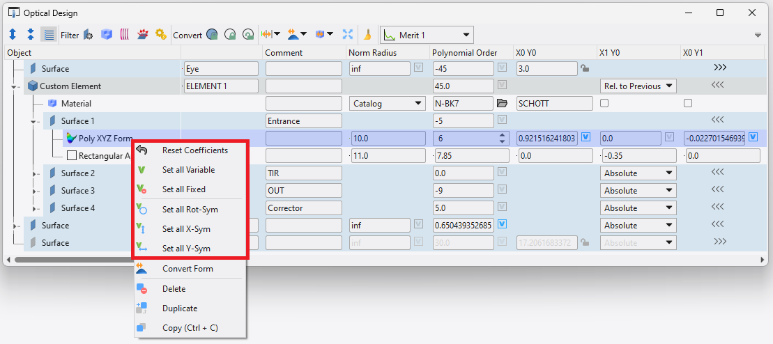
Designing freeform optics usually requires working with large sets of asymmetric polynomial coefficients. It is often necessary to control the polynomial coefficients to be symmetric about one axis or to zero them out to restart from a different solution point. This is a very manual process in traditional optical design programs and can waste considerable time for a conceptually simple task. Quadoa offers a few powerful tools accessed using a right click on the XY polynomial surface form. Users can set all X-symmetric or Y-symmetric coefficients to be variable, remove all variables on a particular surface, or zero out the coefficients altogether. With the iterative nature of designing freeform optics, these simple tools can save a tremendous amount of design time. The image below shows the tools available by right-clicking the XYZ Polynomial surface form.

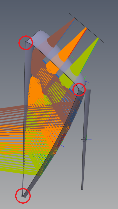
Another critical challenge when designing freeform surfaces is keeping them to manufacturable surface sags. It is very common for optimizers to “run away” with freeform surfaces, especially at the edges of the aperture, when optimizing high order polynomial coefficients. For this reason, it is critical to maintain constraints on the surfaces during the optimization process. Quadoa has a unique 3D distance constraint defined in the merit function that is ideal for this. The user defines an XY point on 2 separate surfaces and the distance between those 2 points in 3D space is returned. This value is independent of ray positions on those surfaces, which is how this would typically be done in traditional optical design programs. Using this capability, it is easy to constrain the edges of 2 freeform surfaces to be close to one another or within some upper and lower bounds. With this capability it is much easier to achieve manufacturable freeform optics than with traditional programs. The image below shows the resulting freeform prism after optimizing with 3D distance constraints at the corners of the 3 freeform surfaces.

Quadoa Optical CAD combines a powerful modeling paradigm with tools that accelerate common tasks to make designing freeform optics faster and more efficient.