The term sequential raytracing is familiar to anyone experienced in the field of optical design. It describes the process of simulating light propagation by tracing rays from one surface to another in a predefined sequence. Originally this was done by hand using YNU tables to calculate ray heights (Y) and angles (U) using lens (or mirror) properties such as index of refraction (N), power (curvature), and thickness. This method of characterizing an optical system, with its many simplifying assumptions, has been fundamental since the earliest days of analytical optical design. When computer programs were eventually written to perform raytracing, the same methodology was implemented. Surfaces were defined in sequential order using index, curvature and thickness. Rays were then traced from one surface to the next in sequential order, albeit with considerably more precision and speed, and fewer approximations. As we’ll explain, this method of raytracing is still useful today, but a modified version called multi-sequential raytracing, used in Quadoa® Optical CAD, radically improves upon it.
The primary benefit of multi-sequential raytracing is the ability to natively define multiple sequences, as the name implies. In the standard sequential raytracing model, there is inherently one ray sequence defined. Modeling more than one ray sequence requires multiple configurations. This works for simple systems but is limiting for a wide range of optical systems. As an illustrative example, let’s consider how we would model an interferometer using sequential and multi-sequential raytracing.

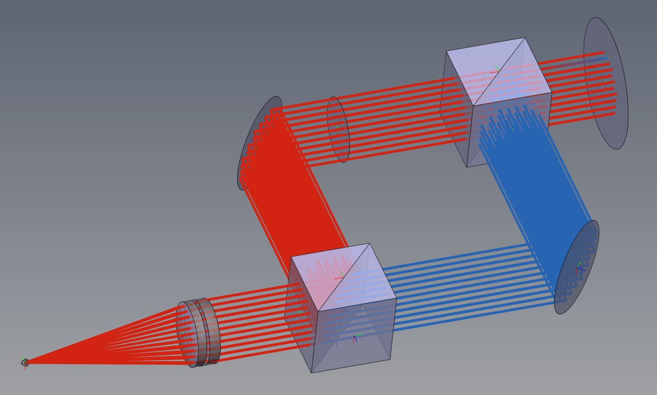
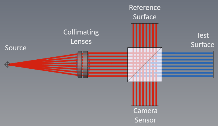
There are two distinct ray paths in this Twyman-Green interferometer. A reference path initially reflects at the beam splitter, then reflects from a reference surface, and finally transmits through the beam splitter before going to a sensor. A test path initially transmits at the beam splitter, then reflects from a surface under test, and finally reflects at the beam splitter before arriving at the sensor. There are 3 aspects of this system that highlight the limitations of standard sequential raytracing and the advantages of multi-sequential raytracing: multiple configurations for multiple paths, double pass duplication, and thickness sign convention.
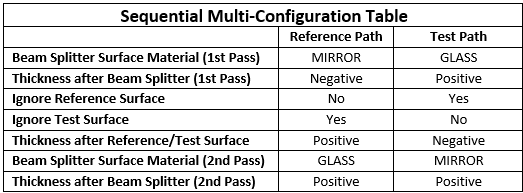
With standard sequential raytracing, multiple optical paths require multiple configurations. Typically, a multi-config table is used to define how parameters (thickness, material, etc.) differ between different configurations. For the beam splitter in our sample file, this requires changing the material of the splitter surface between reference and test ray paths to properly account for transmission or reflection. In the reference path the splitter surface is MIRROR in the first pass, and in the test path it is GLASS. It must be changed again in the second pass. In addition, to model the reference and test surfaces as independent components, each surface must be ignored in the alternate configuration. It is possible to simply rotate the surface from one configuration to the other, but that would require more table entries if other properties of the surfaces differed.
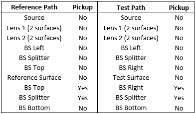
With standard sequential raytracing, surfaces must be replicated each time rays interact with them. For a system where rays reflect and interact with surfaces again, an additional surface is added, typically with solves to ensure it remains at the same location and with the same optical properties. If a tolerance analysis is required and perturbations are needed, this replication becomes very tedious and error-prone. In our interferometer model, the reflected ray paths through the beam splitter require those surfaces to be redefined. Once again, the splitter surface properties must be different between ray paths. For the second pass, in the reference path the splitter surface is GLASS, and in the test path it is MIRROR.
With standard sequential raytracing, the thickness of a surface changes sign with each reflection. This is done to ensure Snell’s law of refraction produces the correct ray direction, but it complicates the optical model. This is another aspect that must be accounted for in the multiple configurations of the optical system. The surface pickups and multi-config table needed to model this interferometer are shown below.


If standard sequential raytracing is this complicated for a relatively simple interferometer, imagine the complexity required for more advanced systems.
Compare all this with the multi-sequential raytrace of this same interferometer in Quadoa. Each optical component (lenses, reference/test surfaces, beam splitter, sensor) is defined a single time with absolute or relative positioning. Separate from this optical model definition, the reference path and test path are defined as user sequences that dictate where the rays go and how they interact with each surface (transmit or reflect). It is this separation of optical model and ray sequences that enables the key benefits of multi-sequential raytracing. Multi-configurations are not required here, though they are supported for systems that genuinely need them (zoom, scanning, thermal, etc.). No surface or component duplication is required. Negative thicknesses are avoided because the program handles the propagation direction based upon the optical model and sequences. Components are placed in whichever coordinate frame of reference is desired.
Multi-sequential raytracing is the evolution of standard sequential raytracing.