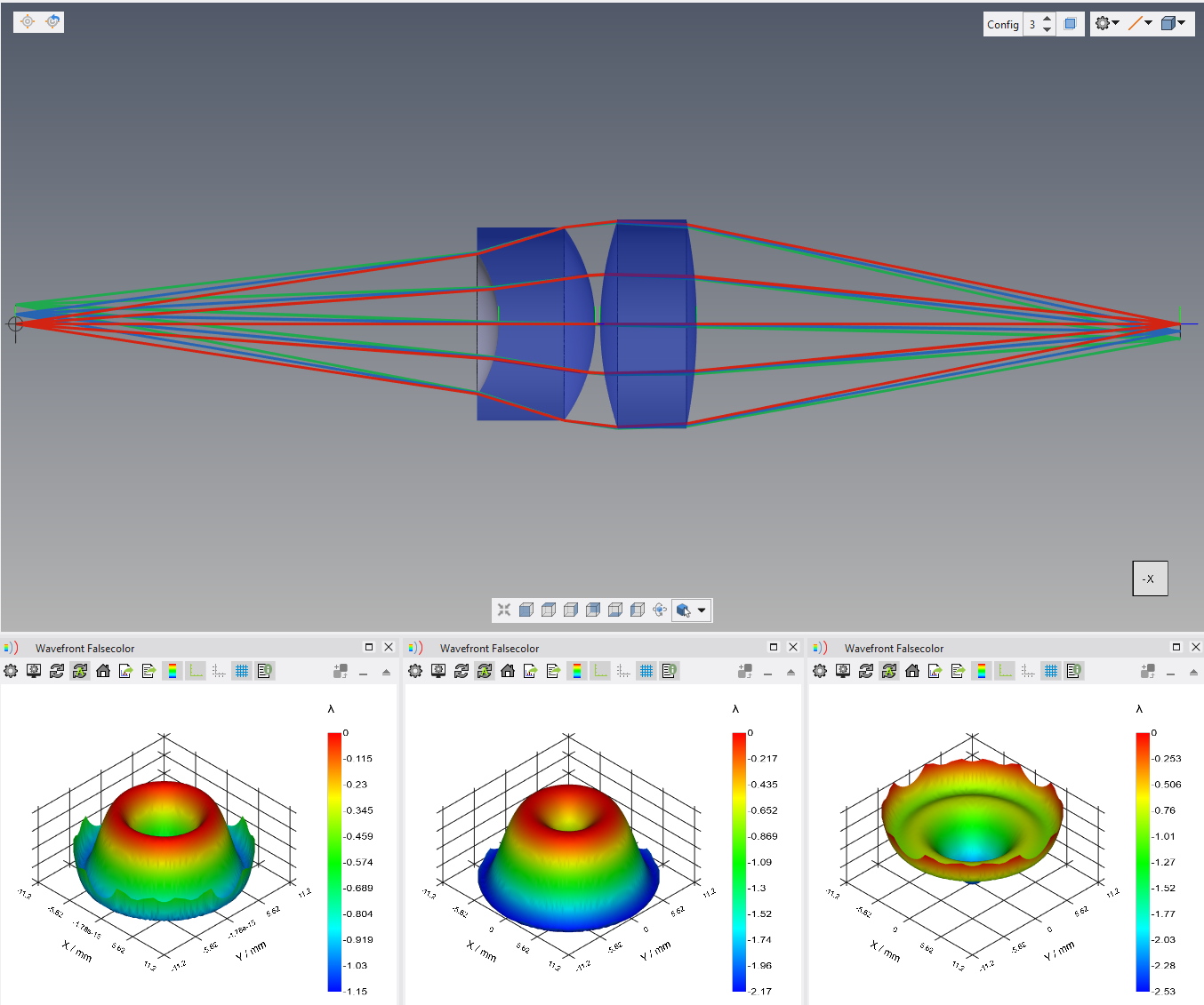
All optical systems are designed to operate under specific environmental conditions. Most often this is at standard temperature and pressure (20 C, 1 Atm). For systems that need to operate across a range of environmental conditions, it is important to account for this during the design process. Failure to do so can result in degraded performance due to defocus and other uncompensated aberrations. Quadoa Optical CAD has capabilities to model, optimize, and tolerance optical systems, including the effects of environmental changes.
To begin, go to File > Open Example and open the following file: Basic_Features/Auto_Sequence.OPTX.
MATERIAL PROPERTIES
Optical system performance changes with temperature due to material property sensitivities. The index of refraction of glass, plastic, and air changes with temperature. In addition, materials have a thermal coefficient of expansion (CTE/TCE) that results in dimensional changes with temperature. In order to simulate thermal impacts to an optical system, it is first necessary to have data that define how the index of materials change with temperature.
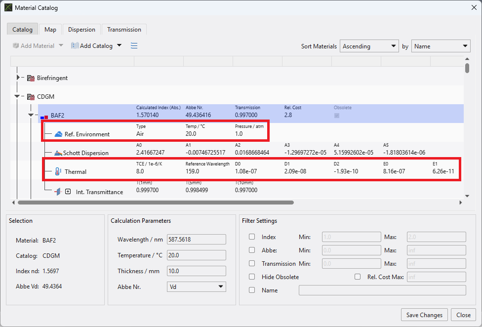
Open Quadoa’s material catalog by going to Setup tab > Materials. Expand the tree for any catalog and material, and note the reference environment and thermal data.

In order for any material to properly account for temperature changes, the TCE and thermal dispersion coefficient data must be defined. This data is defined for most materials in the stock catalogs included with Quadoa. For user-defined materials, these coefficients can be directly defined, or they can be calculated by fitting index versus temperature data. The index of refraction of any component material always takes into account the temperature of the local or global environment. There’s no additional checkbox needed to tell the program to do this. Let’s learn more about how the environmental conditions are specified.
ENVIRONMENT PROPERTIES
Defining the ambient environmental conditions in Quadoa is done in the Environment section of the System Setup Editor (SSE). Open the SSE and note the settings available.

The default environment is Air at standard temperature and pressure. It is possible to define the environment from a catalog material, model material (index, abbe), or from the multi-config table. This environment applies to all elements in the optical system that don’t have a local environment defined. There are two ways to define a local environment. The temperature of any component in the optical design editor (ODE) can be explicitly defined by clicking “Is Thermal” in line with the material definition. This sets the temperature of that component alone.

Alternately, a local environment can be defined by right-clicking on the Environment tree header and selecting “Add Local Environment”; there is also a ribbon bar option in the Setup tab. This allows definition of a local environment that you can add elements to. Simply right-click the Local Environment tree header and select “Place Element”; this option also exists in the Setup tab. Any number of elements can be added to local environment and any number of local environments can be added to an optical model. This method is preferable if there are multiple components that exist in the same environment.

MULTI-CONFIG LOOKUP TABLE
Thermal impacts to optical performance are usually simulated across a sampling of discrete temperatures in an optical system. This is similar to how discrete field points sample a continuous field of view and discrete wavelengths sample a continuous spectrum. In Quadoa this is done in the multi-config lookup table. We have already seen how the system temperature is defined. In order to simulate a range of temperatures, we must define a multi-config parameter that controls the system temperature.
Open the multi-config table from the Setup tab. Start by adding a multi-config parameter using the “PP+” tool in the multi-config table. Afterward, click “C+” twice to add two more configurations. Define the multi-config “ID” parameter using a descriptive name, such as temp. Define the value of this parameter to be 25, 0, and 50 in each configuration.

Once this multi-config parameter is defined, enter it into the Temperature cell controlling the system temperature in the SSE. If done correctly, the parameter name will display along with the current value in parentheses.

Now that the system temperature changes between configurations, take a look at the open wavefront analysis as you change between configurations. Changing configurations can be done by clicking the “Conf N” column headers in the multi-config table. There is also a setting in the 3D viewer to change configuration. Note how the wavefront changes between configurations even though we aren’t yet accounting for thermal expansion/contraction. These changes are due to the change in index of refraction of the two lenses.

As discussed previously, index changes are only one aspect of thermal sensitivities in an optical system. Component and spacer expansion/contraction is also important to take into account.
Accounting for component expansion and contraction with CTE is done by clicking the “Scale Thermally” checkbox inline for any material in the ODE. Activate this setting for both lenses in the optical system. This setting doesn’t scale the surface parameters (radius, coefficients, etc.) directly because this would be very complicated considering the arbitrary form properties that could be applied to a surface. Instead, the scaling is applied to the final surface form, including all stack properties.

Notice how the wavefront maps change once more now that we are including lens CTE effects as well as index effects.

For spacings between components, the expansion or contraction of the gap is controlled by the CTE of the spacer material and the mechanics of the spacer. This can be accounted for in Quadoa by adding a thermal length parameter to the multi-config table. In the multi-config toolbar, click the “Add Thermal Length” tool twice. We will define spacers for both the lens to lens and lens to image spacings.

There are several arguments for the thermal length parameter. The multi-config parameter that defines the system temperature (in our case temp) must be referenced in the “Temp Parameter” cell. The nominal spacing, typically the center thickness, must be transferred from the ODE to the “Nom Length” parameter. There is an “Extra Length” term whose definition depends on what type of mount we are simulating and where it contacts the optical components. The “TEC Type” (CTE) can be user defined, can use a material in the model, or can use a common material (glass, aluminum or steel). The “Nom Temp” must be defined in order to calculate how a change in temperature impacts the spacings. The formula that dictates how the thermal length parameter is calculated is as follows:
L=Lnom+(Lnom+Lext)*CTE*(T-Tnom)
For simplicity we will simulate a spacer that expands only along the z-direction. In this case the additional thickness is just the added sag of the lenses where the spacer contacts them. We can calculate the sag of the lenses using the PTV value reported in the surface form plot (Analysis tab > Form). We combine the sags of lens 1 surface 2 and lens 2 surface 1 for the first extra length parameter. We use only the sag of lens 2 surface 2 for the second extra length parameter. Define the two thermal length parameters as shown here.

Once defined, add these two parameters to the ODE definition of lens 2 z-position and image surface z-position. Again, if defined properly the parameter name will display next to the current value in parentheses.

Take note how the wavefront maps change as we move between configurations now that the expansion/contraction of the spacers is taken into account. You can also see the spacings in parentheses recalculated as we change configuration. We have now fully incorporated thermal effects into our optical design.

ATHERMALIZATION
Athermalization is a related design task that involves optimizing an optical system to achieve best performance across the entire range of operating temperatures. The process is similar to a normal optimization except that we must optimize for all configurations (temperatures) simultaneously. When defining a merit function, each raytrace is performed for one configuration. For a system like the current one, we can add three raytraces, each for a different configuration. When the optimizer is run, it will see performance at all three temperatures and optimize accordingly. Let’s run a quick optimization on the current system.
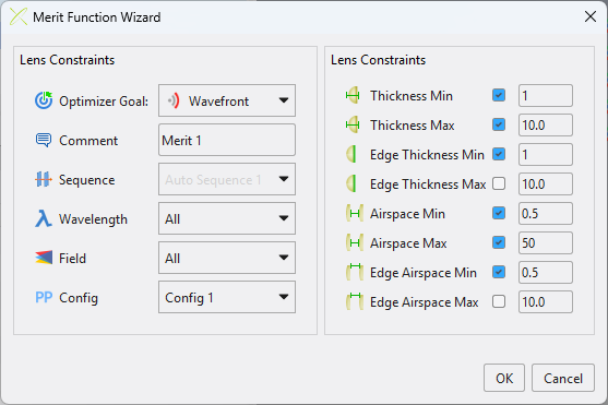
First, delete the existing merit function. Open the merit function wizard in the optimization tab and define the settings as follows.

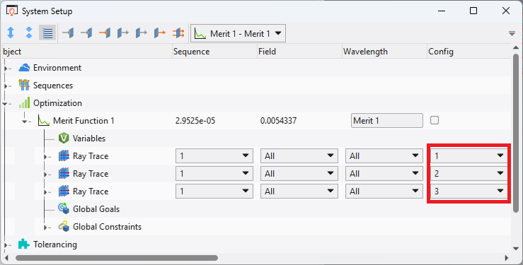
Once this MF is created, expand the merit function section in the SSE and duplicate the raytrace twice; right-click the raytrace header and select duplicate or use CTRL+C then CTRL+V. Change the configuration setting on the new raytrace sections to 2 and 3 as shown below.

Next, we must allocate variables. Set the four lens radii, one conic, two lens thickness, and two air spacings as variable by clicking the V next to their cells. Note the two air spacings are the nominal length parameters defined in the multi-config table. With these variables and merit function, we now optimize for all configurations simultaneously. It’s possible to unequally weight the wavefront goals in each raytrace. For example, the performance at the nominal temperature may be more important than the temperature extremes. Go to Optimization tab > Local Optimization and run the optimizer.

Once the optimizer stops, take a look at the wavefront maps between the different temperature configurations. Quadoa degraded the performance at 25C in order to improve it at 0C and 50C. It is also possible to optimize the lens materials during the optimization process to provide additional performance benefits. This optimization process accounting for multiple temperatures simultaneously is the essence of athermalizing an optical system.
In summary, Quadoa offers several features that enable thermal simulation and athermal optimization of optical systems.